Archive for the ‘Cocoa Coding’ Category

Upgrading Postgres 11.1 to 12.1 Using Homebrew

Tuesday, February 4th, 2020

PostgreSQL.jpg

It's time to make sure that my laptop has the latest version of PostgreSQL, as I was reading that Heroku was moving to Postgres 12 as their default database. And since I don't do it that often, I decided to write it all down so that it's easier to do next time.

The process isn't bad... dump all the databases into one file, stop the server, update Homebrew, update postgres. This gets us to the point that we are ready to rebuild the new database:

  $ pg_dumpall > dump.sql
  $ brew services stop postgresql
  $ brew update
  $ brew upgrade postgres

Now we need to move out the old database data, create a new structure, and restart the service:

  $ cd /usr/local/var
  $ mv postgres postgres.old
  $ initdb -D /usr/local/var/postgres
  $ brew services start postgresql

You then need to go back to the directory of the first command - the one where you dumped the databases, and reload them all:

  $ psql -d postgres -f dump.sql

and at this point, everything should be back and running:

  $ psql --version
  psql (PostgreSQL) 12.1
  $ psql -l
                                      List of databases
      Name     | Owner | Encoding  |    Collate     |     Ctype      |  Access privileges
  -------------+-------+-----------+----------------+----------------+---------------------
   health      | drbob | SQL_ASCII | en_US.US-ASCII | en_US.US-ASCII |
   inventory   | drbob | SQL_ASCII | en_US.US-ASCII | en_US.US-ASCII |
   northhollow | drbob | SQL_ASCII | en_US.US-ASCII | en_US.US-ASCII |
   postgres    | drbob | SQL_ASCII | en_US.US-ASCII | en_US.US-ASCII |
   template0   | drbob | SQL_ASCII | en_US.US-ASCII | en_US.US-ASCII | =c/drbob           +
               |       |           |                |                | drbob=CTc/drbob
   template1   | drbob | SQL_ASCII | en_US.US-ASCII | en_US.US-ASCII | drbob=CTc/drbob    +
               |       |           |                |                | =c/drbob           +
               |       |           |                |                | _postgres=CTc/drbob+
               |       |           |                |                | postgres=CTc/drbob
   test        | drbob | SQL_ASCII | en_US.US-ASCII | en_US.US-ASCII |
  (7 rows)

At this point you can remove the old data:

  $ rm -rf /usr/local/var/postgres.old
  $ rm dump.sql

and everything is updated. You can then use any of the normal tools, including the Apache/PHP/Postgres that Apple makes available, and Postico - a great GUI client.

UPDATE: a friend asked: "What's in 12?" and I had to say I really didn't know... so I looked it up. The big changes are all about under-the-hood performance, and so, as I suspected, it just "works better". Which is really the goal, right? 🙂

I know I will probably enjoy the JIT on by default, as there are plenty of times stored procedures are in my databases, and that makes them faster, which is always nice. But it's just a great database - getting greater.

Trying out a new Editor Font

Tuesday, January 21st, 2020

GeneralDev.jpg

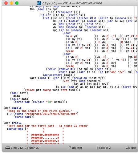
A few days ago, I read about the new JetBrains Mono font that they had created for their IDEs, and it looks interesting with the increased hight of the lower-case letters, and the easily readable "1lI" combination... so I decided to give it a whirl on my editor, and in Xcode.

I have to say I like how Sublime Text and Xcode handles all the weights of the font, and the ligatures for common expressions makes it a lot easier to read the code - as if I'd written it on a chalkboard. Very nice indeed

JetBrains Mono for Clojure

I'm not sure how it'll play out, but it's pretty nice so far, and I'll play with it for a bit and see what I think. So far... nice. 🙂

Potentials – Adding Arrows to Electric Field

Thursday, August 29th, 2019

Building Great Code

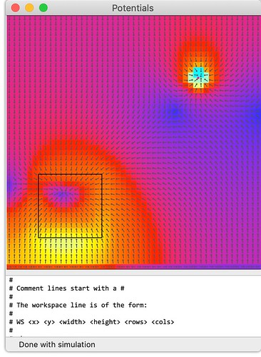
This morning I finished adding in the directional vectors to the display of the electric field on the Potentials app. Previously, we had the color indicate the magnitude of the field at each point, and then the contours were for lines of equal strength. But that's not really all that helpful for an electric field map - better, that each point have a little arrow indicating the direction of the field at that point. Then, you can see the shifting direction of the field, and where a test charge would feel force in the field.

The approach was to start with the points for line segments for the graphics primitives, and then modify them to suit the needs of each point. For example, assume an arrow, pointing to the right, lying on the x-axis, centered at the origin, and fitting with the unit square. There are five endpoints needed to draw these lines in one stroke, so lay them out. This is the starting point for all arrows.

Then we need to rotate it by the angle of the electric field at each point. This is in radians, and we can do this with the CGAffineTransform:

  CGAffineTransformMakeRotation(dir)

where dir is the angle of the field at that point.

Then we can scale the arrow for the size of the box in the view with:

  CGAffineTransformMakeScale(fac, fac)

because we want to look at the minimum size of the box, and call that fac.

Finally, we can move the arrow to the correct place in the view with:

  CGAffineTransformMakeTranslation(x+dx/2.0, y+dy/2.0)

And of course, we can use CGAffineTransformConcat to put these all together into one transformation that can then be applied to each point in the line segment:

  CGAffineTransform    xfrm = CGAffineTransformConcat(
                                CGAffineTransformConcat(
                                  CGAffineTransformMakeRotation(dir), 
                                  CGAffineTransformMakeScale(fac, fac)),
                                CGAffineTransformMakeTranslation(x+dx/2.0, y+dy/2.0));

because you can't call CGAffineTransformConcat with three arguments.

The results are just fantastic:

Electric Field Vectors

and it's easy to track where the test charge will feel the force of the field in every point in the workspace. This is just what we were hoping to get, and it wasn't all that hard with a standard arrow, and then a set of transformations.

Nice. 🙂

Tiny Optimization on Potentials

Wednesday, June 19th, 2019

Speed

This morning I was looking for a little something in the Potentials code, and looked at the following code:

  x = MAX( MAX(_values[r+1][c], _values[r+1][c+1]),
           MAX(_values[r][c], _values[r][c+1]) );

And while it wasn't bad code, the MAX function will execute each argument, and then the winner will be executed again. So while the inner MAX implementations were not really doing any extra work, the outer MAX is causing each of them to be doing more work than necessary.

If we switched from that to the C function fmax:

  x = fmax(fmax(_values[r+1][c], _values[r+1][c+1]),
           fmax(_values[r][c], _values[r][c+1]));

we now know that the inner calls will be executed once, and then the outer is now working with doubles as opposed to macro expansions, and that will make things a little faster - without compromising the readability of the code.

For the traditional test case, the original code reported:

2019-06-19 ...-0500 Potentials[...] [ResultsView -drawRect:] - plot drawn in 18.533 msec

and with the fmax, the results were:

2019-06-19 ...-0500 Potentials[...] [ResultsView -drawRect:] - plot drawn in 16.382 msec

which was a repeatable difference. Now this isn't huge, but it's more than a 10% drop in the execution, so it's not trivial, and more to the point - the redundancy was just unnecessary. Good enough.

Potentials – Accurate Registration

Friday, May 24th, 2019

Building Great Code

For the last several days, I have been noodling on a problem with Potentials that hasn't been the top thing to do - until today. And I wanted to figure this out once and for all, and get things really lined up properly. The problem starts with the simulation grid. It's an nxm grid, where the solution will be calculated on each of the grid points - exactly. It's then up to me to visually represent that as best I can.

The initial code took each of these points and created a rectangle for each on the viewport of the NSView, and then selected the best color, and filled in that rectangle. So far, so good.

But then the contour lines required that we take groups of 4 points and (possibly) draw a line in the box they defined. Now we have a problem. As you look at the box for a contour line, it will be "colored" by the node value in the lower-left corner. Not ideal. This means that there would be a row, and a column, of rectangles that represent the edge nodes of the simulation - but no way to put contour lines in those boxes.

The solution was to treat the rectangle fill the same way as the contour lines - to take all four points in each square and compute a single value for the painting that rectangle. For a first cut, it seemed reasonable to have a simple MAX() function of all four values - yes, this will inflate the effect of an isolated node, but that's OK... it's the maximum value - in that area. I can live with that.

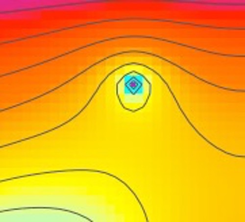
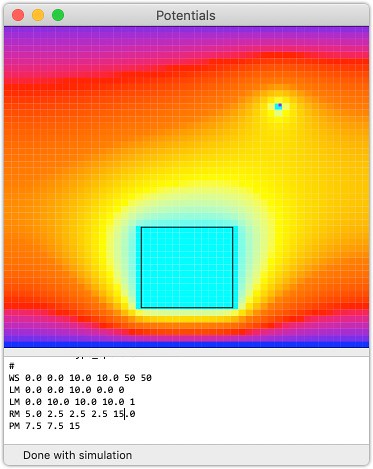
The results are really nice. The contour lines and the items under simulation and colors line up very nicely. This is a blown up section around the point conductor in the example:

Potentials Registration

At the same time, the contour lines now go to the edge of the display, as they should, and if I need to change the algorithm for the colorization of the rectangles - based on the four point values - that's easy enough to change.

Looking better and better. 🙂

Potentials – Respect the Ratio

Wednesday, May 22nd, 2019

Building Great Code

Today I noticed that the display code for Potentials was filling the display viewport - and distorting the shapes in the simulation. For example, a "square" could be made to look like a long rectangle, simply by resizing the window. This wasn't right. So today I spent a little time to fix this.

The code wasn't that hard, and to save a little time, I computed the drawing "origin" as well as the scale factor for the drawing to the NSView so that each part of the drawing didn't have to recompute these. Nothing fancy - just scale to the one dimension that will fit in the viewport, and then fix that, adjust everything else.

Potentials where the Ratio is Right

At this point, you can see the added white "letter boxing" on the window as we have respected the ratio of the workspace, and the drawing is being constrained in the vertical dimension. Simple, but very nice.

Little by little, it's getting better. 🙂

Sometimes… Performance Tuning is Just Exercise

Wednesday, May 22nd, 2019

Speed

This morning, I was taking another crack at increasing the performance of the graphing in Potentials, as my initial tests of just draw red seemed to show that I could cut a significant amount of time off the drawing, if I didn't have to allocate all those NSColor objects. Seemed like a reasonable thing to try, and after all... performance tuning can be fun.

So it's not like the CGColor or NSColor would allow me to directly access the values of red, green, and blue - so I had to move them from the NSColor instance into a simple array of CGFloat values. No big deal - now I'm passing around a simple, fixed-size array that is easily indexed, and because I can make them on the stack, there's no way these are leaking.

Then I needed to peel back the existing methods on ResultsView and make it so that they allowed for passing in, and returning, arrays of CGFloat values. Again, this is a simple refactoring, as I could then simply use these new methods within the existing methods, and I didn't loose any capabilities of using NSColor arguments. Still good.

Finally, I was then able to update the drawing method and have it convert the input colors to linear space, and arrays of CGFloat values, and then run the same processing on these arrays of CGFloats, and we had what we'd hoped for.

Almost.

What I saw was that there was 2 msec difference - out of 17+ msec - that this changed. Nothing. So I backed out the changes, and realized that I had a new respect for the macOS developers - they have really tuned this machine to make the AppKit/Foundation way of doing things about as fast as humanly possible - and the difference with just plotting red was that of a single color versus a range. This was the case all along, and I was mistakenly thinking that I was seeing some effect that wasn't really there.

So it's not faster... but I am wiser about the inner workings of macOS and drawing, and I'll be sure to remember this in the future. 🙂

Potentials – Smoother Contour Lines

Monday, May 20th, 2019

Building Great Code

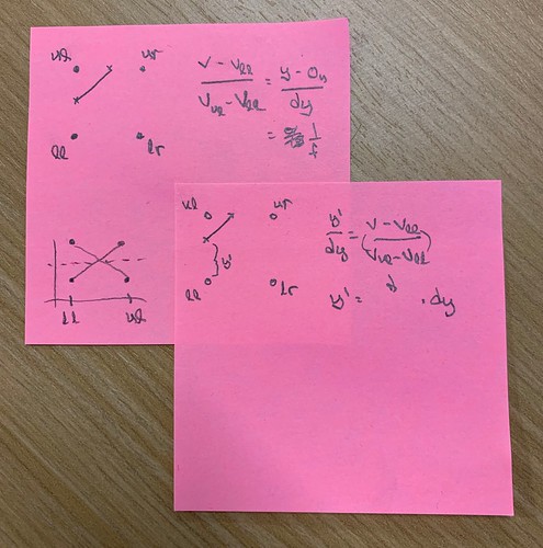
Today at lunch, I was scanning the class notes on the Contour Lines I'd used in Potentials, and I was thinking that their solution of sub-dividing the grid ever smaller - until you get to the resolution of the display was nice, but that there was a better way - analog. Meaning, to ratio the value of the contour, and the relative values of the grid points. My notes were pretty simple:

Contour Lines Notes

And when we look at the previous work, it's clear where the nodes are, as it's crude, and not very smooth at all. But when we take the values from the data and then test them:

  // grab the four corner values from the data
  vul = _values[r+1][c];
  vur = _values[r+1][c+1];
  vll = _values[r][c];
  vlr = _values[r][c+1];
  // now compute the in/out state of the four corners
  ul = (vul < value);
  ur = (vur < value);
  ll = (vll < value);
  lr = (vlr < value);

then the code for the individual line segments of the contour are simply:

  // line from left to top
  sy = (value - vll)/(vul - vll);
  pbeg = NSMakePoint(x, y+dy*sy);
  sx = (value - vul)/(vur - vul);
  pend = NSMakePoint(x+dx*sx, y+dy);

where the effect of sx and sy are to modify the value from 0.5 in the previous version, which is half-way between nodes, to that percentage represented by the values of the nodes, and the contour. This makes a huge difference:

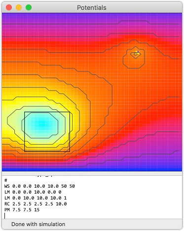
Potentials with Smooth Contours

And it's just amazing how much nicer it looks. The code isn't doing anything that complex - it's just doing the work a little smarter... and that is just elegant.

Potentials – Added Contour Lines

Wednesday, May 15th, 2019

Building Great Code

Today I spent some time refactoring the [ResultsView -drawRect:] method in Potentials as it was a monster method with all kinds of access to ivars, and lots of code - and it really needed to have setters and getters, and the code needed to be broken up so that it was a lot easier to manipulate and compose. That wasn't too bad. Then it was time to look at the Contour Lines.

I ran across this slide deck for a class from the University of Edinburgh on this exact subject. Turns out it was a lot simpler than I had thought. By simply using the gridding I'd used for the solution, it was possible to think of the contours as separators and not just lines of "constant value" - because then it comes down to 16 different patterns where the state of each node value with respect to a threshold is concerned.

Then it was a simple task of drawing the lines, and boom! Done!

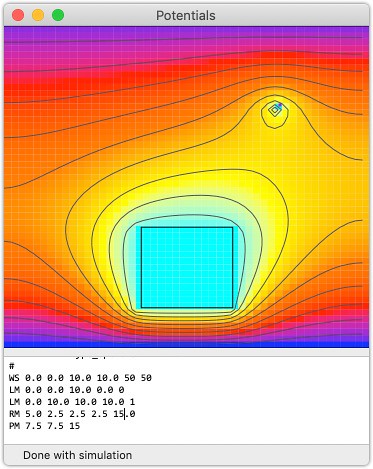
Potentials with Contour lines

Sure... there's a lot I can do to make this nicer - reduce the gird size... go non-uniform mesh and refine the mesh based on the magnitude of the electric field, and at less than 10 msec per solution set, I could easily refine this 5 or 6 times and come up with something really pretty nice.

But Wow... this has been something I've wanted for years... and now it's checked-in, and it runs faster than I ever would have imagined. Life is good. 🙂

Potentials – Adding the Inventory

Thursday, May 9th, 2019

Building Great Code

The latest addition to Potentials has been that of the outlines of the elements in the simulation - lines, points, rectangles, etc. These can be charge sheets, conductors, dielectrics, etc. - but until now, only their effects have been seen. The point is to make these items visible on their own, so that their boundaries can be seen, as well as their effects.

Since all these had to be in-place in the context of the -drawRect: method on the NSView subclass, it meant that we had to be passed in with the plotting data that was the results of the simulation. In order to make this scale well, with redraws of the NSView, we needed to pass this in with [0..1] on the linear dimensions of the drawing surface.

What we settled on was to add to the BaseSimObj a method:

/*!
 This method returns an NSDictionary with the Quartz 2D drawing data
 and keys to indicate *how* to draw that object. The axis measurements
 are normalized to [0..1] so that scaling this is very easy, and it's
 placed in the workspace so that as that region is drawn, this object
 is in the correct location. This is essential so that this guy can
 be drawn on the simulation results.
 */
- (NSDictionary*) drawingInfo:(SimWorkspace*)ws;

so that each type of object could place itself in the drawing space on the unit axes. The data is returned as an NSDictionary because it's simply a few pieces - the type of drawing needed to be done, and the data for that drawing. Here is the line's implementation:

- (NSDictionary*) drawingInfo:(SimWorkspace*)ws
{
  if (ws != nil) {
    NSRect        wsr = [ws getWorkspaceRect];
    NSPoint       beg = [self getStartPoint];
    NSPoint       end = [self getEndPoint];
    // map the point to [0..1] on each axis for plotting
    beg.x = (beg.x - wsr.origin.x)/wsr.size.width;
    beg.y = (beg.y - wsr.origin.y)/wsr.size.height;
    end.x = (end.x - wsr.origin.x)/wsr.size.width;
    end.y = (end.y - wsr.origin.y)/wsr.size.height;
    return @{@"draw" : @"line",
             @"from" : [NSValue valueWithPoint:beg],
             @"to" : [NSValue valueWithPoint:end]};
  }
  // there's nothing we can possibly do without a workspace
  return nil;
}

where the required key is draw, and that is a simple NSString of the type of drawing to do, which will then be interpreted in the -drawRect: method. Simple.

Another is the rectangle:

- (NSDictionary*) drawingInfo:(SimWorkspace*)ws
{
  if (ws != nil) {
    NSRect        wsr = [ws getWorkspaceRect];
    NSRect        rect;
    rect.size = [self getSize];
    // move the center of the rect to the origin for the NSRect
    rect.origin = [self getLocation];
    rect.origin.x -= rect.size.width/2.0;
    rect.origin.y -= rect.size.height/2.0;
    // map the point to [0..1] on each axis for plotting
    rect.origin.x = (rect.origin.x - wsr.origin.x)/wsr.size.width;
    rect.origin.y = (rect.origin.y - wsr.origin.y)/wsr.size.height;
    rect.size.width /= wsr.size.width;
    rect.size.height /= wsr.size.height;
    return @{@"draw" : @"rect",
             @"data" : [NSValue valueWithRect:rect]};
  }
  // there's nothing we can possibly do without a workspace
  return nil;
}

and as long as the drawing data can be put into an NSDictionary, we're good to go.

Then we needed to add a section to the -drawRect: method that would look at the list of all the items in the inventory, and for each, look at their drawing directions, and draw them in the context. This is the code for the first one - a line:

  for (NSDictionary* info in [self getInventory]) {
    // everything draws to the view, scaled on the
    NSString* draw = info[@"draw"];
    if ([draw isEqualToString:@"line"]) {
      // get the specifics for the line from the data
      NSPoint     beg = [info[@"from"] pointValue];
      NSPoint     end = [info[@"to"] pointValue];
      // map it to the viewport for drawing
      beg.x *= sx;
      beg.y *= sy;
      end.x *= sx;
      end.y *= sy;
      CGPoint     line[] = {beg, end};
      NSLog(@"[ResultsView -drawRect:] - drawing line inventory: (%.2f, %.2f) ->
              (%.2f, %.2f)", beg.x, beg.y, end.x, end.y);
      // draw the line in the viewport
      CGContextBeginPath(myContext);
      CGContextSetLineWidth(myContext, 1.0);
      CGContextSetRGBStrokeColor(myContext, 0.0, 0.0, 0.0, 1.0);
      CGContextAddLines(myContext, line, 2);
      CGContextStrokePath(myContext);

The interesting addition here is that when drawing a path, you really have to begin the path, add the path elements, and then stroke the path. Not bad, but it took a little bit to find that in an example to make the elements visible.

In the end, we now have the inventory:

Potentials with Inventory

And the speed is impressive. The simulations are being calculated in under 5 msec, and the drawing is being done in under 14 msec. This means that it's going to be possible to make a graphical builder - eventually, and have the results appear quite nicely. 🙂